

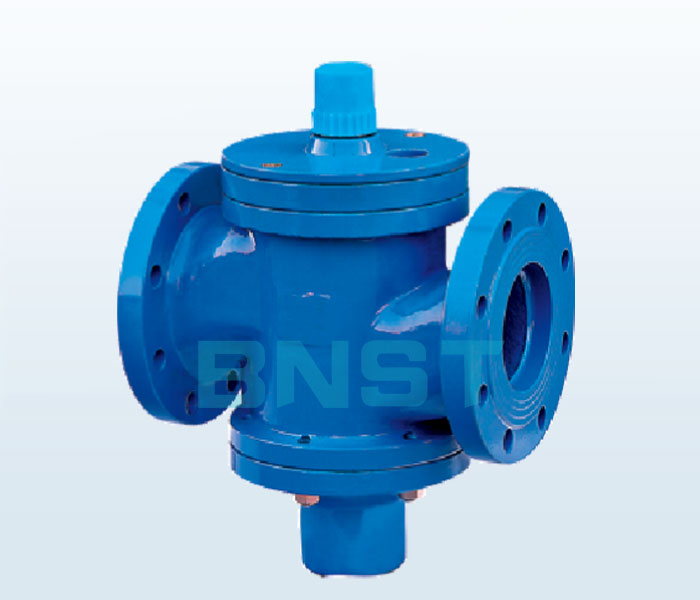
Self-standing balancing valve
Self-standing balancing valve
ZLF-16 self-operated flow balance valve, also known as self-operated balance valve, flow control valve, flow controller, dynamic balance valve, flow balance valve, is an intuitive and simple flow adjustment control device, application in pipe network The self-operated flow balance valve can directly set the flow according to the design.
Product Overview:
ZLF-16 self-operated flow balance valve, also known as self-operated balance valve, flow control valve, flow controller, dynamic balance valve, flow balance valve, is an intuitive and simple flow adjustment control device, application in pipe network The self-operated flow balance valve can directly set the flow according to the design. The valve can automatically eliminate the flow deviation caused by the residual head and pressure fluctuation of the pipeline under the action of water. The set flow rate is maintained regardless of the change of the system pressure. These functions of the self-operated flow balance valve make the pipe network flow adjustment complete once, and the network adjustment work becomes a simple flow distribution, effectively solving the hydraulic imbalance of the pipe network. Self-operated flow balance valve is mainly used in: centralized heating (cold) and other water systems, so that the pipe network flow can be distributed as needed, eliminating the hydraulic imbalance of the water system, solving the problem of uneven heat and cold, saving energy and saving 15%-20 %.
Product features: The
flow can be set according to the design or actual requirements, which can automatically eliminate the pressure difference fluctuation of the system and keep the flow rate unchanged.
Overcome the uneven heat and cold of the system and improve the quality of heating (cooling).
Thoroughly resolve the contradiction between large pressure difference at the proximal end and small pressure difference at the distal end.
Reduce system circulation and reduce system resistance.
Reduce the amount of design work, without the need for cumbersome hydraulic balance calculations on the pipe network.
Reduce the difficulty of network adjustment, simplifying complex network adjustment work into simple traffic distribution.
It eliminates the redistribution of traffic when the heat source of the multi-heat source network is switched.
The flow display values are all randomly calibrated on the test bench, flow rate (m3/h).
Technical parameters :
| Body form | Straight through casting body |
| Nominal diameter | DN15~350mm |
| Nominal pressure | PN1.0, 1.6 MPa |
| Flange standard | ANSI, JIS, DIN, GB, JB (specially available by user) |
| Connection Type | Flange (FF RF RTJ), thread (for DN25) |
| Medium temperature | 0 to 150 ° C |
| Working pressure difference | 20~600KPa |
| Flow accuracy | 5% |
Main parts materials:
| Bottom cover | Cast iron, ductile iron, cast steel |
| spring | 65Mn/60Si2Mn |
| Valve body | Cast iron, ductile iron, cast steel |
| Seat | 2Cr13, 304 |
| Spool | 2Cr13, 304 |
| Valve stem | 2Cr13, 304 |
| Gasket | Flexible graphite, polytetrafluoroethylene |
| Sealing packing | V-type PTFE filler, asbestos textile filler, graphite filler |
Main shape and connection size and weight:
| Nominal diameter (DN) | Installation method | L(mm) | H1 (mm) | H2 (mm) | Constant flow | Weight (Kg) |
| 15 | Threaded connection | 100 | 60 | 50 | 0.2-1 | 0.6 |
| 20 | 110 | 60 | 50 | 0.3-1.5 | 0.6 | |
| 25 | 115 | 60 | 50 | 0.5-2 | 0.7 | |
| 32 | Flange connection | 130 | 70 | 70 | 1-4 | 4 |
| 40 | 200 | 90 | 100 | 1.5-6 | 11 | |
| 50 | 215 | 100 | 105 | 2-8 | 12 | |
| 65 | 230 | 130 | 110 | 3-12 | 15 | |
| 80 | 275 | 159 | 170 | 5-20 | 27 | |
| 100 | 290 | 175 | 185 | 10-30 | 30 | |
| 125 | 310 | 180 | 200 | 15-45 | 40 | |
| 150 | 350 | 210 | 220 | 30-70 | 63 | |
| 200 | 425 | 230 | 285 | 40-180 | 104 | |
| 250 | 480 | 310 | 385 | 100-300 | 189 | |
| 300 | 650 | 405 | 480 | 150-500 | 218 | |
| 350 | 700 | 420 | 545 | 200-700 | 265 |

| Address: No.8-7, Runyang New Town, No.507, Jiankang West Street, Weicheng District, Weifang, Shandong | 
|
|

Copyright 2019, www.bonasite.cn, all rights reserved; Lu ICP 19005870, without consent, may not be reproduced